Operational Test of the ELACs A320
WARNING: MAKE SURE THAT THE TRAVEL RANGES OF THE FLIGHT CONTROLS SURFACES ARE CLEAR. MOVEMENT OF FLIGHT CONTROLS CAN CAUSE INJURY TO PERSONS AND/OR DAMAGE TO EQUIPMENT.
1. Reason for the Job
Self explanatory
2. Job Set-up Information
A. Fixtures, Tools, Test and Support Equipment
| REFERENCE | QTY | DESIGNATION |
| No specific | 1 | ACCESS PLATFORM 2M (6 FT) — ADJUSTABLE |
B. Work Zones and Access Panels
| ZONE/ACCESS | ZONE DESCRIPTION |
| 210 | CKPT,FWD COMPT BHD TO FLT COMPT BULKHEAD |
| 822 |
C. Referenced Information
| REFERENCE | DESIGNATION |
| Ref. 24-41-00-861-002-A | Energize the Aircraft Electrical Circuits from the External Power |
| Ref. 24-41-00-861-002-A01 | Energize the Aircraft Electrical Circuits from the APU |
| Ref. 24-41-00-861-002-A02 | Energize the Aircraft Electrical Circuits from Engine 1(2) |
| Ref. 24-41-00-862-002-A | De-energize the Aircraft Electrical Circuits Supplied from the External Power |
| Ref. 24-41-00-862-002-A01 | De-energize the Aircraft Electrical Circuits Supplied from the APU |
| Ref. 24-41-00-862-002-A02 | De-energize the Aircraft Electrical Circuits Supplied from the Engine 1(2) |
| Ref. 29-10-00-863-003-A | Pressurize the Blue Hydraulic System with a Hydraulic Ground Power-Cart |
| Ref. 29-10-00-863-003-A01 | Pressurize the Blue Hydraulic System with the Blue Electric Pump |
| Ref. 29-10-00-864-003-A | Depressurize the Blue Hydraulic System |
| Ref. 29-23-00-863-001-A | Pressurize the Green Hydraulic System from the Yellow Hydraulic System through the PTU with the Electric Pump |
| Ref. 29-23-00-864-001-A | Depressurize the Green and Yellow Hydraulic Systems after Operation of the PTU |
| Ref. 29-24-00-863-001-A | Pressurize the Yellow Hydraulic System with the Electric Pump |
| Ref. 29-24-00-864-001-A | Depressurize the Yellow Hydraulic System |
| Ref. 31-60-00-860-001-A | EIS Start Procedure |
| Ref. 31-60-00-860-002-A | EIS Stop Procedure |
3. Job Set-up
SUBTASK 27-93-00-860-052-A
A. Aircraft Maintenance Configuration
(1) Energize the aircraft electrical circuits Ref. AMM TASK 24-41-00-861-002.
(2) Depressurize the aircraft hydraulic systems Ref. AMM TASK 29-23-00-864-001 Ref. AMM TASK 29-24-00-864-001 Ref. AMM TASK 29-10-00-864-003.
SUBTASK 27-93-00-010-050-A
B. Get Access
(1) Put the ACCESS PLATFORM 2M (6 FT) — ADJUSTABLE in position at the access door 822.
(2) Open the access door 822.
(3) On the battery power center 105VU:
— Loosen the two screws and remove the protective cover.
SUBTASK 27-93-00-865-050-A
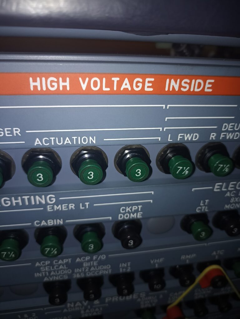
C. Make sure that this(these) circuit breaker(s) is(are) closed:
| PANEL | DESIGNATION | FIN | LOCATION |
| 49VU | FLIGHT CONTROLS/ELAC1/NORM/SPLY | 15CE1 | B11 |
| 49VU | FLIGHT CONTROLS/THS/ACTR/MOT2 | 19CE2 | B09 |
| 105VU | FLIGHT CONTROLS/ELAC2/STBY SPLY | 16CE2 | A02 |
| 105VU | FLT CTL/ELAC1/STBY SPLY | 16CE1 | A01 |
| 121VU | FLIGHT CONTROLS/THS ACTR/MOT1 | 19CE1 | Q16 |
| 121VU | FLIGHT CONTROLS/ELAC2/NORM/SPLY | 15CE2 | R20 |
SUBTASK 27-93-00-860-053-A
D. Aircraft Maintenance Configuration
(1) On the overhead panel 23VU:
— Release the FLT CTL/ELAC 1 and FLT CTL/SEC 1 pushbutton switches (on these pushbutton switches, the OFF legend comes on).
(2) On the overhead panel 24VU:
— Release the FLT CTL/ELAC 2, FLT CTL/SEC 2 and FLT CTL/SEC 3 pushbutton switches (on these pushbutton switches, the OFF legend comes on).
(3) Do the EIS start procedure Ref. AMM TASK 31-60-00-860-001.
(4) On the center pedestal, on the ECAM control panel, push the F/CTL key (on the lower ECAM display unit, the F/CTL page comes into view).
4. Procedure
SUBTASK 27-93-00-710-050-A
A. Operational Test of the Elevator Aileron Computers (ELACs)
NOTE: This test is for ELAC1. For ELAC2, use the indications between the parentheses.
| ACTION | RESULT |
| 1.On the overhead panel 23VU (24VU): | On the overhead panel 23VU (24VU): |
| -Push the FLT CTL/ELAC 1 (2) pushbutton switch. | -The OFF legend of the FLT CTL/ELAC 1 (2) pushbutton switch goes off-The FAULT legend of the FLT CTL/ELAC 1 (2) pushbutton switch comes on between 3 to 8 seconds, then goes off. |
| 2.On the overhead panel 23VU (24VU): | On the overhead panel 23VU (24VU): |
| -Release the FLT CTL/ELAC 1 (2) pushbutton switch. | -The OFF legend of the FLT CTL/ELAC 1 (2) pushbutton switch comes on. |
| 3.Pressurize the aircraft hydraulic systems Ref. AMM TASK 29-23-00-863-001 Ref. AMM TASK 29-24-00-863-001 Ref. AMM TASK 29-10-00-863-003. | |
| 4.Move the THS in the nose up direction, with the handwheel. | The THS moves. |
| 5.On the overhead panel 23VU (24VU): | On the overhead panel 23VU (24VU): |
| -Push the FLT CTL/ELAC 1 (2) pushbutton switch. | -The OFF legend of the FLT CTL/ELAC 1 (2) pushbutton switch goes off. |
| On the center pedestal:-The pitch trim control wheels move to 0. | |
| On the lower ECAM display unit, on the F/CTL page, on the pitch trim indicator:-The position of the THS moves to 0° plus or minus 0.3 | |
| The THS moves to 0. | |
| 6.On the CAPT side:-Move the side stick to the right until it touches the stop. | On the lower ECAM display unit:-The index of the right aileron moves up, the index of the left aileron moves down. |
| -Release the side stick. | -The indexes of the left and right ailerons move to the neutral position. |
| -Move the side stick to the left until it touches the stop. | -The index of the left aileron moves up, the index of the right aileron moves down. |
| -Release the side stick. | -The indexes of the left and right ailerons go back to the neutral position. |
| -Pull the side stick rearward until it touches the stop. | -The indexes of the left and right elevators move up. |
| -Release the side stick. | -The indexes of the left and right elevators go back to the neutral position. |
| -Push the side stick forward until it touches the stop. | -The indexes of the left and right elevators move down. |
| -Release the side stick. | -The indexes of the left and right elevators go back to the neutral position. |
| On the upper ECAM display unit, no warning comes into view. | |
| 7.On the F/O side:-Move the side stick to the right until it touches the stop. | On the lower ECAM display unit-The index of the right aileron moves up, the index of the left aileron moves down. |
| -Release the side stick. | -The indexes of the left and right ailerons go back to the neutral position. |
| -Move the side stick to the left until it touches the stop. | -The index of the left aileron moves up, the index of the right aileron moves down. |
| -Release the side stick. | -The indexes of the left and right ailerons go back to the neutral position. |
| -Pull the side stick rearward until it touches the stop. | -The indexes of the left and right elevators move up. |
| -Release the side stick. | -The indexes of the left and right elevators go back to the neutral position. |
| -Push the side stick forward until it touches the stop. | -The indexes of the left and right elevators move down. |
| -Release the side stick. | -The indexes of the left and right elevators go back to the neutral position. |
| On the upper ECAM display unit, no warning comes into view. | |
| 8.On the overhead panel 24VU (23VU): | On the overhead panel 24VU (23VU): |
| -Push the FLT CTL/ELAC 2 (1) pushbutton switch. | -The OFF legend of the FLT CTL/ELAC 2 (1) pushbutton switch goes off. |
5. Close-up
SUBTASK 27-93-00-860-054-A
A. Put the aircraft back to its initial configuration.
(1) On the overhead panel 23VU:
— Push the FLT CTL/SEC 1 pushbutton switch (on this pushbutton switch, the OFF legend goes off).
(2) On the overhead panel 24VU:
— Push the FLT CTL/SEC 2 and FLT CTL/SEC 3 pushbutton switches (on these pushbutton switches, the OFF legend goes off).
(3) Depressurize the aircraft hydraulic systems Ref. AMM TASK 29-23-00-864-001 Ref. AMM TASK 29-24-00-864-001 Ref. AMM TASK 29-10-00-864-003.
(4) Do the EIS stop procedure Ref. AMM TASK 31-60-00-860-002.
(5) De-energize the aircraft electrical circuits Ref. AMM TASK 24-41-00-862-002.
SUBTASK 27-93-00-410-050-A
B. Close Access
(1) Install the protective cover on the battery power center 105VU.
(2) Tighten the two screws.
(3) Close the access door 822.
(4) Remove the access platform(s).