
Operational Test of the Slat System A320
WARNING: PUT THE SAFETY DEVICES AND THE WARNING NOTICES IN POSITION BEFORE YOU START A TASK ON OR NEAR:
— THE FLIGHT CONTROLS
— THE FLIGHT CONTROL SURFACES
— THE LANDING GEAR AND THE RELATED DOORS
— COMPONENTS THAT MOVE.
MOVEMENT OF COMPONENTS CAN KILL OR CAUSE INJURY TO PERSONS AND/OR CAN CAUSE DAMAGE TO THE EQUIPMENT.
1. Reason for the Job
Self Explanatory
2. Job Set-up Information
A. Fixtures, Tools, Test and Support Equipment
| REFERENCE | QTY | DESIGNATION |
| No specific | AR | SAFETY BARRIER(S) |
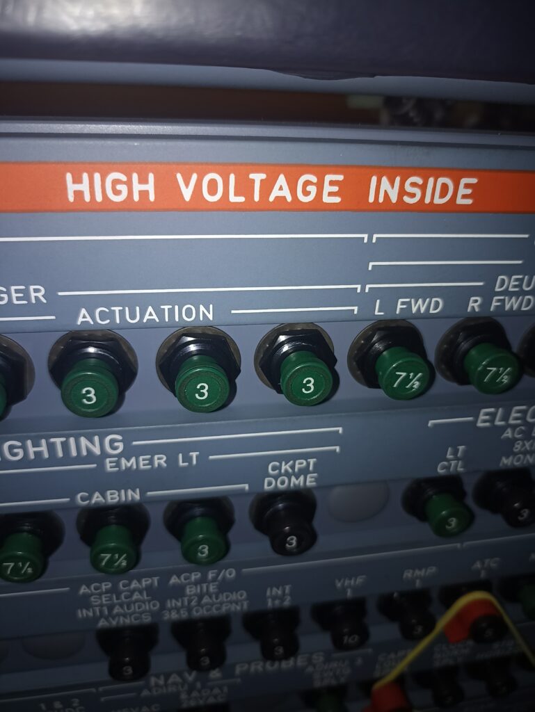
| No specific | AR | SAFETY CLIP — CIRCUIT BREAKER |
| No specific | AR | WARNING NOTICE(S) |
B. Referenced Information
| REFERENCE | DESIGNATION |
| Ref. 24-41-00-861-002-A | Energize the Aircraft Electrical Circuits from the External Power |
| Ref. 24-41-00-861-002-A01 | Energize the Aircraft Electrical Circuits from the APU |
| Ref. 24-41-00-861-002-A02 | Energize the Aircraft Electrical Circuits from Engine 1(2) |
| Ref. 24-41-00-862-002-A | De-energize the Aircraft Electrical Circuits Supplied from the External Power |
| Ref. 24-41-00-862-002-A01 | De-energize the Aircraft Electrical Circuits Supplied from the APU |
| Ref. 24-41-00-862-002-A02 | De-energize the Aircraft Electrical Circuits Supplied from the Engine 1(2) |
| Ref. 29-10-00-863-001-A | Pressurize the Green Hydraulic System with a Hydraulic Ground Power-Cart |
| Ref. 29-10-00-863-002-A | Pressurize the Yellow Hydraulic System with a Hydraulic Ground Power-Cart |
| Ref. 29-10-00-863-003-A | Pressurize the Blue Hydraulic System with a Hydraulic Ground Power-Cart |
| Ref. 29-10-00-863-003-A01 | Pressurize the Blue Hydraulic System with the Blue Electric Pump |
| Ref. 29-10-00-864-001-A | Depressurize the Green Hydraulic System |
| Ref. 29-10-00-864-002-A | Depressurize the Yellow Hydraulic System |
| Ref. 29-10-00-864-003-A | Depressurize the Blue Hydraulic System |
| Ref. 29-23-00-863-001-A | Pressurize the Green Hydraulic System from the Yellow Hydraulic System through the PTU with the Electric Pump |
| Ref. 29-23-00-864-001-A | Depressurize the Green and Yellow Hydraulic Systems after Operation of the PTU |
| Ref. 29-24-00-863-001-A | Pressurize the Yellow Hydraulic System with the Electric Pump |
| Ref. 31-60-00-860-001-A | EIS Start Procedure |
3. Job Set-up
SUBTASK 27-84-00-941-050-A
A. Safety Precautions
(1) As necessary, use the applicable SAFETY BARRIERS, specified by the operator’s instructions and your local regulations.
(2) Put the WARNING NOTICE(S) in position to tell persons that the slat system is in operation.
SUBTASK 27-84-00-860-052-A
B. Aircraft Maintenance Configuration
(1) Energize the aircraft electrical circuits Ref. AMM TASK 24-41-00-861-002.
(2) Pressurization of the hydraulic systems
NOTE: Make sure that the hydraulic pressure is sufficient to move the slats.
(a) Pressurize the Yellow hydraulic system Ref. AMM TASK 29-10-00-863-002 or Ref. AMM TASK 29-24-00-863-001.
(b) Pressurize the Blue hydraulic system Ref. AMM TASK 29-10-00-863-003.
(c) Pressurize the Green hydraulic system Ref. AMM TASK 29-10-00-863-001 or Ref. AMM TASK 29-23-00-863-001.
SUBTASK 27-84-00-865-050-A
C. Open, safety and tag this(these) circuit breaker(s):
| PANEL | DESIGNATION | FIN | LOCATION |
| 49VU | FLIGHT CONTROLS/FLP/CTL AND MONG/SYS1 | 6CV | B07 |
| 49VU | AUTO FLT/FAC1/26VAC | 14CC1 | B03 |
| 121VU | AUTO FLT/FAC2/26VAC | 14CC2 | M18 |
| 121VU | FLIGHT CONTROLS/FLP/CTL AND/MONG/SYS2 | 8CV | Q21 |
SUBTASK 27-84-00-865-052-A
D. Make sure that this(these) circuit breaker(s) is(are) closed:
| PANEL | DESIGNATION | FIN | LOCATION |
| 49VU | FLIGHT CONTROLS/SLT/CTL AND MONG/SYS1 | 5CV | B06 |
| 121VU | FLIGHT CONTROLS/WTB/SLT/SYS2 | 11CV | P19 |
| 121VU | FLIGHT CONTROLS/SLT/CTL/SYS2 | 7CV | R21 |
| 122VU | FLIGHT CONTROLS/WTB/SLT/SYS1 | 9CV | S06 |
4. Procedure
SUBTASK 27-84-00-710-050-A
A. Operational Test of the Slat System
WARNING: MAKE SURE THAT THE TRAVEL RANGES OF THE FLIGHT CONTROLS SURFACES ARE CLEAR. MOVEMENT OF FLIGHT CONTROLS CAN CAUSE INJURY TO PERSONS AND/OR DAMAGE TO EQUIPMENT.
CAUTION: IF THE THRUST REVERSER COWLS ARE OPEN, MAKE SURE THAT THE HALF DOORS OF THE THRUST REVERSER ARE CLOSED BEFORE YOU EXTEND THE SLATS. IF THE DOORS ARE OPEN, YOU CAN CAUSE DAMAGE TO THE SLATS AND HALF DOORS WHEN THE SLATS EXTEND.
(1) Do the EIS start procedure (upper ECAM DU and lower ECAM DU only) Ref. AMM TASK 31-60-00-860-001.
(2) Do this test:
| ACTION | RESULT |
| 1.On the center pedestal on the panel 114VU: | |
| -move the slat and flap control lever to the position 1 and then to the position 2. Stop at each notch until the slats are in their new position. | -the slats move to the set position.On the ECAM upper DU:-the slat position bar moves to the set position-the new position of the lever and the travel direction of the slats are shown. |
| 2.On the panel 114VU: | |
| -move the slat and flap control lever to the position 3. | -the slats do not move.On the ECAM upper DU:-the slat position bar does not move-the new position of the lever is shown as above. |
| 3.On the panel 114VU: | |
| -move the slat and flap control lever to the position FULL. | -the slats move to the set position.On the ECAM upper DU:-the slat position bar moves to the set position-the new position of the lever and the travel direction of the slats are shown. |
| 4.On the panel 114VU: | |
| -move the slat and flap control lever back to the position 3. | -the slats move to the set position.On the ECAM upper DU:-the slat position bar moves to the set position-the new position of the lever and the travel direction of the slats are shown-no warnings related to the slat system are shown. |
| 5.On the panel 114VU: | |
| -move the slat and flap control lever back to the position 2. | -the slats do not move.On the ECAM upper DU:-the slat position bar does not move-the new position of the lever is shown. |
| 6.On the panel 114VU: | |
| -move the slat and flap control lever back to the positions 1 and 0. Stop at each notch until the slats are in their new position. | -the slats move to the set position.On the ECAM upper DU:-the slat position bar moves to the set position-the new position of the lever and the travel direction of the slats are shown-no warnings related to the slat system are shown. |
5. Close-up
SUBTASK 27-84-00-860-053-A
A. Put the aircraft back to its initial configuration.
(1) Depressurize the Yellow hydraulic system Ref. AMM TASK 29-10-00-864-002.
(2) Depressurize the Blue hydraulic system Ref. AMM TASK 29-10-00-864-003.
(3) Depressurize the Green hydraulic system Ref. AMM TASK 29-10-00-864-001 or Ref. AMM TASK 29-23-00-864-001.
(4) Do the EIS stop procedure Ref. AMM TASK 31-60-00-860-001.
(5) De-energize the aircraft electrical circuits Ref. AMM TASK 24-41-00-862-002.
SUBTASK 27-84-00-865-051-A
B. Remove the safety clip(s) and the tag(s) and close this(these) circuit breaker(s):
| PANEL | DESIGNATION | FIN | LOCATION |
| 49VU | FLIGHT CONTROLS/FLP/CTL AND MONG/SYS1 | 6CV | B07 |
| 49VU | AUTO FLT/FAC1/26VAC | 14CC1 | B03 |
| 121VU | AUTO FLT/FAC2/26VAC | 14CC2 | M18 |
| 121VU | FLIGHT CONTROLS/FLP/CTL AND/MONG/SYS2 | 8CV | Q21 |
SUBTASK 27-84-00-942-050-A
C. Removal of Equipment
(1) Remove the safety barriers.
(2) Remove the WARNING NOTICE(S).
(3) Remove the ground support and maintenance equipment, the special and standard tools and all other items.