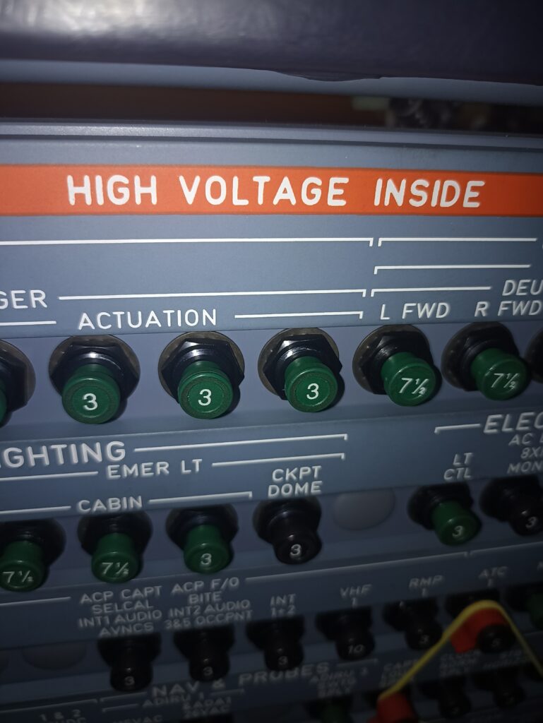

Operational Test of the FCDC A320
1. Reason for the Job
Self explanatory
2. Job Set-up Information
A. Work Zones and Access Panels
| ZONE/ACCESS | ZONE DESCRIPTION |
| 210 | CKPT,FWD COMPT BHD TO FLT COMPT BULKHEAD |
B. Referenced Information
| REFERENCE | DESIGNATION |
| Ref. 24-41-00-861-002-A | Energize the Aircraft Electrical Circuits from the External Power |
| Ref. 24-41-00-861-002-A01 | Energize the Aircraft Electrical Circuits from the APU |
| Ref. 24-41-00-861-002-A02 | Energize the Aircraft Electrical Circuits from Engine 1(2) |
| Ref. 24-41-00-862-002-A | De-energize the Aircraft Electrical Circuits Supplied from the External Power |
| Ref. 24-41-00-862-002-A01 | De-energize the Aircraft Electrical Circuits Supplied from the APU |
| Ref. 24-41-00-862-002-A02 | De-energize the Aircraft Electrical Circuits Supplied from the Engine 1(2) |
| Ref. 31-60-00-860-001-A | EIS Start Procedure |
| Ref. 31-60-00-860-002-A | EIS Stop Procedure |
3. Job Set-up
SUBTASK 27-96-00-860-058-A
A. Aircraft Maintenance Configuration
(1) Energize the aircraft electrical circuits Ref. AMM TASK 24-41-00-861-002.
(2) On the overhead panel, on FLT CTL panel 23VU, make sure that the ELAC 1 and SEC 1 pushbutton switches are pushed (the OFF and FAULT legends are off).
(3) On the overhead panel, on FLT CTL panel 24VU, make sure that the ELAC 2, SEC 2 and SEC 3 pushbutton switches are pushed (the OFF and FAULT legends are off).
(4) Do the EIS start procedure Ref. AMM TASK 31-60-00-860-001.
SUBTASK 27-96-00-865-055-A
B. Make sure that this(these) circuit breaker(s) is(are) closed:
| PANEL | DESIGNATION | FIN | LOCATION |
| 49VU | FLIGHT CONTROLS/ELAC1/NORM/SPLY | 15CE1 | B11 |
| 49VU | FLIGHT CONTROLS/FCDC1/SPLY | 20CE1 | B10 |
| 49VU | FLIGHT CONTROLS/SEC1/NORM/SPLY | 21CE1 | B08 |
| 121VU | PTR/SPLY | 6TW | J21 |
| 121VU | CFDS/CFDIU/SPLY | 2TW | J18 |
| 121VU | CFDS/CFDIU/BACK/UP | 8TW | J17 |
| 121VU | FLIGHT CONTROLS/FCDC2/SPLY | 20CE2 | Q20 |
| 121VU | FLIGHT CONTROLS/SEC3/SPLY | 21CE3 | Q19 |
| 121VU | FLIGHT CONTROLS/SEC2/SPLY | 21CE2 | Q18 |
| 121VU | FLIGHT CONTROLS/ELAC2/NORM/SPLY | 15CE2 | R20 |
4. Procedure
SUBTASK 27-96-00-710-055-A
A. Do this test:
| ACTION | RESULT |
| 1.On the circuit breaker panel 121VU:- Open the C/B 20CE2. | On the upper ECAM display unit:- The F/CTL FCDC2 FAULT message is shown. |
| 2.On the center pedestal, on the ECAM control panel:- Push the F/CTL key. | On the lower ECAM display unit, the F/CTL page comes into view.Make sure that:- There are no crosses on the EFCS servocontrols.On the upper ECAM display unit, make sure that:- No F/CTL FCDC1 FAULT message is shown. |
| 3.On the circuit breaker panel 121VU:- Close the C/B 20CE2. | On the upper ECAM display unit:- The F/CTL FCDC2 FAULT message goes out of view. |
| 4.On the circuit breaker panel 49VU:- Open the C/B 20CE1. | On the upper ECAM display unit:- The F/CTL FCDC1 FAULT message is shown.- Make sure that no F/CTL FCDC2 FAULT message is shown.On the lower ECAM display unit, on the F/CTL page:- Make sure that there are no crosses on the EFCS servocontrols. |
| 5.On the circuit breaker panel 49VU:- Close the C/B 20CE1. | On the upper ECAM display unit:- The F/CTL FCDC1 FAULT message goes out of view. |
5. Close-up
SUBTASK 27-96-00-860-059-A
A. Put the aircraft back to its initial configuration.
(1) Do the EIS stop procedure Ref. AMM TASK 31-60-00-860-002.
(2) De-energize the aircraft electrical circuits Ref. AMM TASK 24-41-00-862-002.