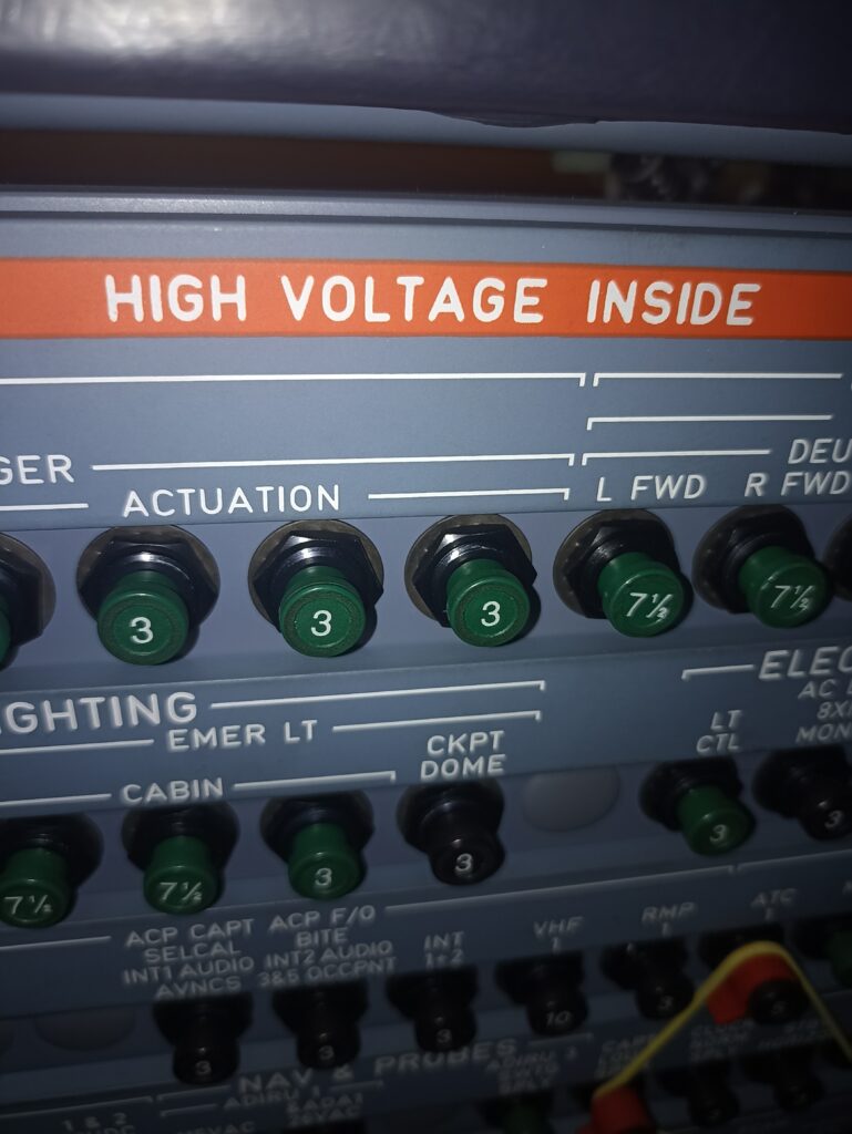

Failure of the Radio Altimeter (RA) Transceiver 1 A320
1. Possible Causes:
-XCVR-RA, 1 (2SA1)
-short to ground at the wiring between the circuit breaker (1SA1) and the RA transceiver 1 (2SA1).
-C/B-COM NAV/RAD ALTM/1
2. Job Set-up Information
A. Referenced Information
| REFERENCE | DESIGNATION |
| Ref. 31-32-00-810-934-A | Failure of the Digital Links |
| Ref. AMM 34-42-00-740-002 | BITE Test of the Radio Altimeter |
| Ref. ASM 34-42-01 | |
| Ref. AMM 34-42-33-000-001 | Removal of the Radio Altimeter Transceiver |
| Ref. AMM 34-42-33-400-001 | Installation of the Radio Altimeter Transceiver |
3. Fault Confirmation
SUBTASK 34-42-00-865-050-A
A. Make sure that this(these) circuit breaker(s) is(are) closed:
| PANEL | DESIGNATION | FIN | LOCATION |
| 121VU | COM NAV/RAD ALTM/1 | 1SA1 | K11 |
SUBTASK 34-42-00-740-050-A
B. Test
(1) If the circuit breaker (1SA1) trips, refer to Para. 4. C. of this trouble shooting procedure.
(2) Do the BITE test of the radio altimeter Ref. AMM 34-42-00-740-002.
— If the BITE test is not possible, refer to Para. 4. B. of this trouble shooting procedure.
4. Fault Isolation
SUBTASK 34-42-00-810-050-B
A. If the circuit breaker (1SA1) is closed, and if the BITE test gives the maintenance message RA 1 (2SA1).
— replace the XCVR-RA, 1 (2SA1) Ref. AMM 34-42-33-000-001 and Ref. AMM 34-42-33-400-001.
SUBTASK 34-42-00-810-051-A
B. If the circuit breaker (1SA1) is closed and if the BITE test is not possible
— do a check for 115VAC at pin AC/8 of the RA transceiver 1.
(1) If there is no 115VAC:
— do a check of the wiring of the 115VAC signal from circuit breaker (1SA1) to RA transceiver 1 (2SA1) Ref. ASM 34-42-01.
(a) If there is no continuity:
— repair the above wiring.
(b) If there is continuity:
— replace the C/B-COM NAV/RAD ALTM/1 (1SA1).
(2) If there is 115VAC:
— do a check of the wiring of the ground signal at RA transceiver 1 pin AC/3.
(a) If there is no continuity:
— repair the above wiring.
(b) If there is continuity:
1 do the trouble shooting procedure Ref. TSM TASK 31-32-00-810-934 related to:
- the output Bus signal ALTITUDE BUS 1 (2) Ref. ASM 34-42-01
SUBTASK 34-42-00-810-082-A
C. If the circuit breaker (1SA1) is open:
— close this circuit breaker.
(1) If the circuit breaker (1SA1) trips:
— remove the XCVR-RA, 1 (2SA1) Ref. AMM 34-42-33-000-001.
— close the circuit breaker (1SA1).
(a) If this circuit breaker stays closed:
— install the RA transceiver 1 Ref. AMM 34-42-33-400-001
1 If the circuit breaker trips again:
— replace the RA transceiver 1 Ref. AMM 34-42-33-000-001 and Ref. AMM 34-42-33-400-001.
(b) If this circuit breaker trips again:
— do a check for a short to ground at the wiring between the circuit breaker (1SA1) and the RA transceiver 1 (2SA1). Ref. ASM 34-42-01.
1 If there is a short to ground:
— repair the above wiring.
2 If there is no short to ground:
— replace the C/B-COM NAV/RAD ALTM/1.
3 Install the RA transceiver 1 Ref. AMM 34-42-33-400-001.
SUBTASK 34-42-00-740-051-A
D. Do the test given in Para. 3.B.